The structural analysis software RFEM 6 is the basis of a modular software system. The main program RFEM 6 is used to define structures, materials, and loads of planar and spatial structural systems consisting of plates, walls, shells, and members. The program also allows you to create combined structures as well as to model solid and contact elements.
RSTAB 9 is a powerful analysis and design software for 3D beam, frame, or truss structure calculations, reflecting the current state of the art and helping structural engineers meet requirements in modern civil engineering.
Do you often spend too long calculating cross-sections? Dlubal Software and the RSECTION stand-alone program facilitate your work by determining section properties of various cross-sections and performing a subsequent stress analysis.
Do you always know where the wind is blowing from? From the direction of innovation, of course! With RWIND 2, you have a program at your side that uses a digital wind tunnel for the numerical simulation of wind flows. The program simulates these flows around any building geometry and determines the wind loads on the surfaces.
Are you looking for an overview of snow load zones, wind zones, and seismic zones? Then you are in the right place. Use the Geo-Zone Tool to determine quickly and efficiently snow loads, wind speeds, and seismic data according to ASCE 7‑16 and other international standards.
Would you like to try out the capabilities of the Dlubal Software programs? You have the opportunity to do so! The free 90-day full version allows you to thoroughly test all our programs.
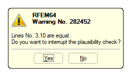
It may happen that surfaces are not connected, though they should be. In this respect, double lines may have an effect on the calculation. It is better to clean the model and remove all double lines.
You can find double lines quickly using the feature "Tools → Model Check → Overlapping Lines". This tool also allows you to export the line pairs as an Excel list or create partial views (see the highlighted buttons in Image 02).
However, it is often not easy to delete the lines, as they are assigned to different objects. Thus, if you delete one of the lines, you also delete a surface, for example. Therefore, you should first check all structural components to see whether the lines can be deleted, and change the boundary lines, if necessary. In the attached video, you can see how the boundary lines of the surfaces can be exchanged quickly. The remaining double line can then be deleted easily.